Introduction
Ceramics are among the most challenging materials to prepare for metallographic analysis. Their extreme hardness, brittleness, and tendency to chip or crack require specialized techniques throughout the entire preparation process. Unlike metals, ceramics often require diamond tools at every stage, very slow cutting speeds, and extended grinding and polishing times.
Key Challenge: Ceramics are extremely hard and brittle. They require diamond blades for sectioning, very slow cutting speeds to prevent chipping, and extended grinding and polishing times. Special care must be taken to avoid cracking and pullout of hard phases.
Common ceramic materials include alumina (Al₂O₃, ~2000 HV), zirconia (ZrO₂, ~1200-1500 HV), silicon carbide (SiC, ~2500-3000 HV), silicon nitride (Si₃N₄, ~1500-1800 HV), boron carbide (B₄C, ~2800 HV), and various oxide ceramics. Each type has specific hardness and brittleness characteristics that influence preparation. For example, silicon carbide is among the hardest ceramics and requires the most aggressive diamond abrasives, while zirconia may be more susceptible to phase transformation under stress. The fundamental principles remain the same: minimize mechanical damage, prevent chipping, and reveal grain boundaries without pullout.
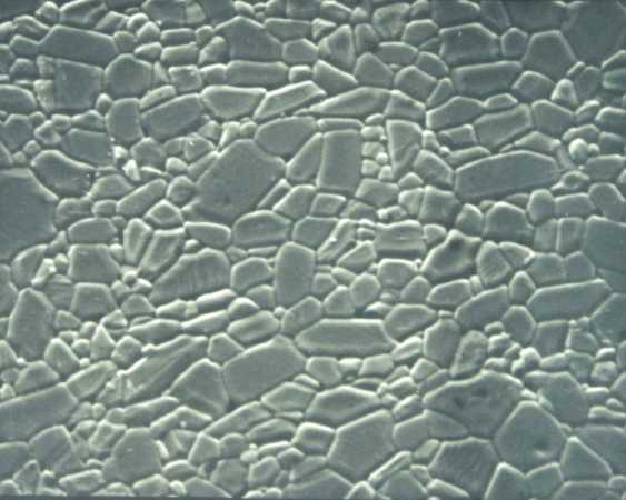
Alumina (Al₂O₃) ceramic microstructure showing grain boundaries, properly prepared and etched. Ceramics require specialized preparation techniques to reveal grain boundaries without chipping or pullout.
Ceramic Material Characteristics
- Alumina (Al₂O₃): Very hard (~2000 HV), chemically stable, commonly used in wear applications
- Zirconia (ZrO₂): High toughness for a ceramic, may undergo phase transformation, requires careful handling
- Silicon Carbide (SiC): Extremely hard (~2500-3000 HV), requires aggressive diamond abrasives throughout
- Silicon Nitride (Si₃N₄): High strength and hardness, good thermal shock resistance
- Boron Carbide (B₄C): One of the hardest known materials (~2800 HV), extremely challenging to prepare
- Porous Ceramics: May require vacuum impregnation during mounting to prevent pullout
This guide will walk you through the complete preparation process, with special emphasis on the unique challenges ceramics present and how to overcome them.
Sectioning
Sectioning ceramics is one of the most critical steps. Bulk monolithic ceramics require diamond blades; softer ceramics (glasses, hydroxyapatite, many refractories, low-density Al2O3) can be cut with hardened alumina abrasive wheels. For thin ceramic coatings on metal substrates, choose the blade for the substrate; an alumina abrasive wheel (MAX-D) works well since the ceramic represents only a small fraction of the cross-section.
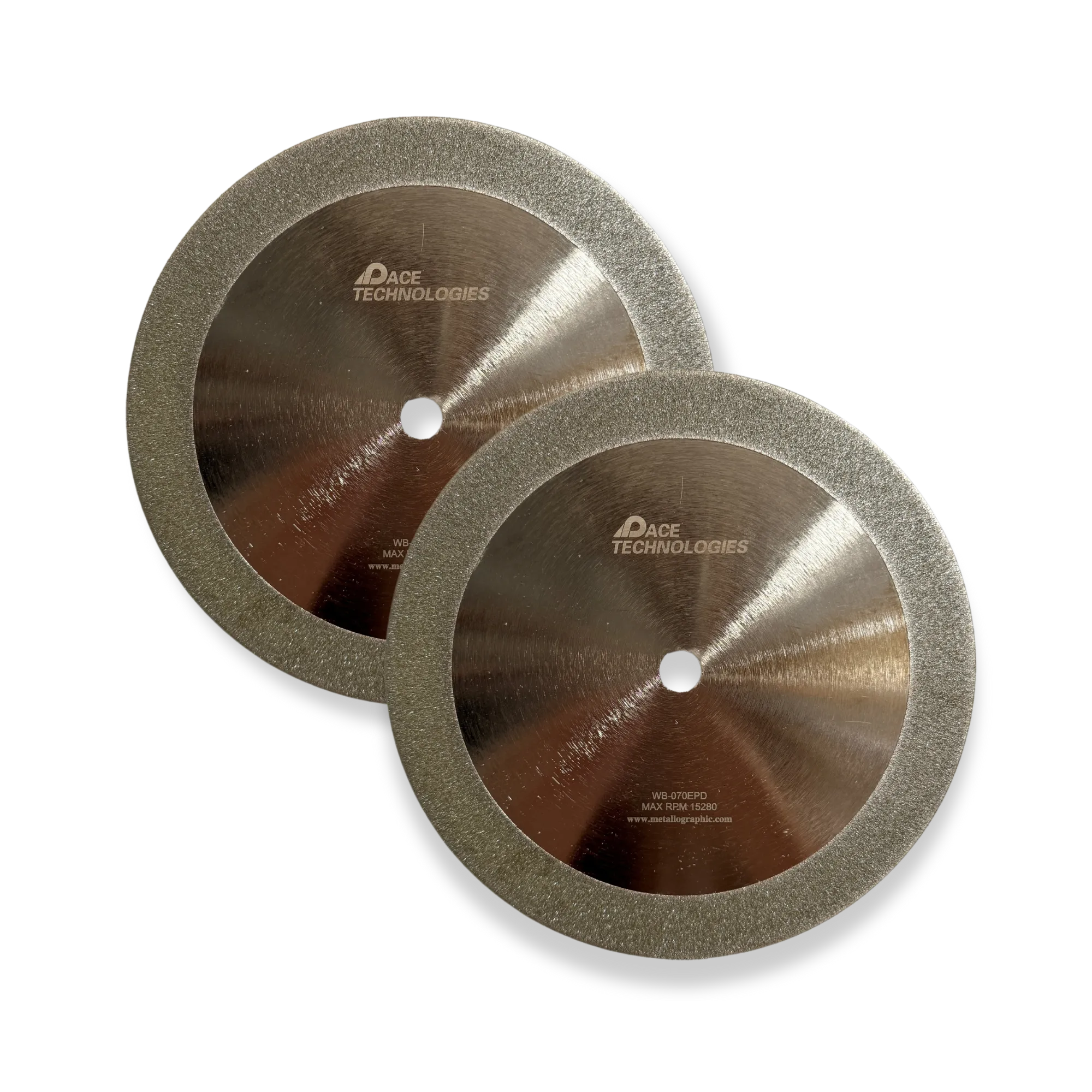
Diamond cut-off blades for sectioning dense structural ceramics. Resin-bonded diamond for general ceramic work, metal-bonded diamond for the hardest grades (SiC, B4C).
Cutting Parameters
- Blade Type: Diamond-impregnated cut-off wheels for dense structural ceramics. Resin-bonded diamond for general work; metal-bonded or electroplated diamond for the hardest grades (SiC, B4C). For ceramic coatings on metal substrates, alumina abrasive wheels (MAX-D) are usually sufficient.
- Wheel Speed: 200-400 RPM on a precision wafering saw; 2500-3500 RPM on a conventional metallographic cutoff machine. Wheel speed itself rarely causes chipping; feed rate and lateral support do.
- Feed Rate: Slow and steady. 5-20 mm/min on a precision saw for most ceramics; reduce to 2-10 mm/min for thin, fragile, or thermal-shock-sensitive samples (Si3N4, ZrO2).
- Cooling: Continuous, copious coolant flow is essential to prevent thermal shock. Water-based cutting fluid is standard; some refractories absorb water and benefit from a light oil coolant.
- Blade Thickness: Thin precision blades (0.3-0.5 mm) minimize kerf loss and chipping at the cut exit. Thicker blades (0.5-0.8 mm) give more lateral stability on large or irregular samples.
- Blade Condition: Use sharp, freshly dressed diamond blades. Worn blades generate excessive heat, smear material, and cause chipping. Dress the blade after sectioning hard substrates if it goes immediately into a fragile ceramic.
- Clamping: Use a thin styrofoam or rubber pad between the clamp and the ceramic to distribute pressure and prevent clamp-induced cracks.
Best Practices
- Match the blade to the ceramic: resin-bonded diamond for general work, metal-bonded for the hardest grades, alumina abrasive for soft ceramics or coatings on metal.
- Use a precision saw with slow controlled feed for thin sections, fragile parts, or where chip-free cuts are critical.
- Apply minimal force; let the diamond do the cutting. Excessive force causes chipping and blade wear far more than wheel speed does.
- Maintain continuous coolant flow throughout the cut to prevent thermal shock cracking, especially in Si3N4 and ZrO2.
- Support the sample so the cut exits into supported material; unsupported exit edges chip badly in dense ceramics.
- For anisotropic ceramics (some SiC grades, single-crystal materials), consider cutting direction relative to crystal orientation if it matters to the analysis.
- Inspect immediately after cutting for chips or cracks at the cut edge; if present, plan to grind them out in the plane-grinding step.
Important: Chipping during sectioning is often irreparable. Take your time and use the slowest practical cutting speed. It's better to spend extra time sectioning than to have to start over with a new sample.
For more information on sectioning blades, visit our Diamond Cut-Off Blades collection.
Mounting
For most ceramic work, castable (cold) mounting with low-viscosity epoxy is preferred over hot compression mounting. The thermal cycle and pressure of compression mounting can crack thin sections, propagate existing micro-cracks, and damage fragile microstructures. Hot compression mounting is acceptable for dense, robust samples (bulk Al2O3, sintered SiC) where edge retention is the primary concern.
Mounting Material Selection
- Castable epoxy (cold mount): First choice for fragile, thin, or porous ceramics; ceramic coatings; and samples with pre-existing cracks. Eliminates thermal stress entirely. Low-viscosity formulations infiltrate small pores and cracks.
- Mineral-filled epoxy (hot, edge retention): For dense, robust ceramics where edge retention near the mount boundary is critical. The hard filler particles polish at a rate close to the ceramic, eliminating the matrix-mount step that causes edge rounding.
- Phenolic: Acceptable for routine work on robust ceramics; not preferred for fragile or quantitative work.
- Conductive resins: Required for SEM/EDS analysis of nonconductive ceramics; use carbon- or copper-filled compression resin, or apply a conductive paint bridge after mounting.
Compression Mounting (when used)
- Clean the sample thoroughly with alcohol or acetone.
- Inspect for chips or cracks from sectioning; if severe, start over rather than mount damaged material.
- Select an appropriate mold size (typically 1.25" or 1.5" diameter).
- Place sample in mold with the analysis surface facing down on the ram.
- Use mineral-filled epoxy for best edge retention.
- Mount at 150-180 °C, 2000-3000 psi.
- Hold 5-8 minutes at temperature; cool slowly under pressure (10-15 minutes) before releasing.
Castable (Cold) Mounting
- Clean and dry the sample thoroughly.
- Place in mounting cup with the analysis surface facing down.
- Mix low-viscosity castable epoxy per manufacturer instructions.
- Pour over the sample, ensuring complete coverage.
- Cure at room temperature (typically 4-8 hours; overnight for best results).
Vacuum Impregnation for Porous Ceramics
Mandatory for porous ceramics (filters, refractories, biomedical implants, ceramic foams, thermal barrier coatings, hydroxyapatite). Without it, air-filled pores collapse during grinding and polishing, debris pumps in and out of pores on every revolution, and apparent porosity reads low while pullout reads high.
- Place the sample in the mounting cup; do not yet add hardener if the resin's pot life is short.
- Place the cup in a vacuum impregnation chamber and draw vacuum to 25-100 mbar.
- Hold under vacuum for 1-5 minutes; watch for bubble evolution from the pore network. When bubbling stops, the pores are degassed.
- Slowly release vacuum to atmospheric. The pressure differential drives resin into the evacuated pore network.
- Cure at room temperature per resin specification.
Fluorescent dye visualization: Mix a small amount of fluorescent epoxy dye into the castable epoxy before mounting. Under blue-pass / orange-pass illumination in the microscope, voids that were infiltrated by resin glow yellow, while pulled-out grains and dried-debris voids remain dark. This is the standard technique for distinguishing real porosity from preparation artifacts. Limitation: Some ceramics are translucent, in which case the entire sample fluoresces and the technique loses contrast, particularly an issue for thin or low-density Al2O3.
For more information on mounting equipment, visit our Compression Mounting Equipment page.
Grinding
For dense structural ceramics (SiC, B4C, dense Al2O3, dense Si3N4), diamond grinding on a rigid disc is the right approach. For softer ceramics (glasses, hydroxyapatite, many oxide refractories, porous ceramics), SiC paper still works and may give better results because the rigid disc loads quickly on soft material. Match the abrasive to the hardness.
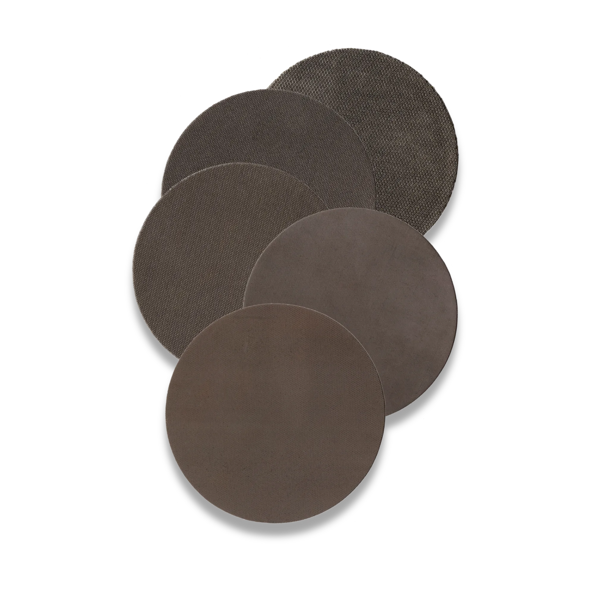
Metal-bonded diamond grinding disc: the rigid alternative to coarse SiC paper for hard ceramics. Gives flatter samples with less subsurface damage than progressive SiC sequences.
Grinding Sequence: Hard Ceramics (SiC, B4C, dense Al2O3, dense Si3N4)
- Plane grind with CERMESH metal mesh cloth (~75 μm DIAMAT diamond): 1-3 minutes until plane, 30-40 N per sample, 300 RPM, water lubricant. Removes sectioning damage; replaces a long SiC sequence.
- 15 μm diamond on rigid composite disc: 3-5 minutes, 30-40 N per sample, 150 RPM, DIAMAT polycrystalline diamond suspension.
- 9 μm diamond on SIRIUS composite disc: 3-5 minutes, same parameters. This step transitions directly to diamond polishing.
Grinding Sequence: Softer or Porous Ceramics
- 240 grit SiC paper (P280-P320): Until plane, water lubricant, 5-10 lbs per sample, 200-300 RPM.
- 400 grit SiC paper (P500): 1-2 minutes, same parameters.
- 600 grit SiC paper (P1200): 1-2 minutes, same parameters.
Grinding Parameters
- Abrasive choice: Diamond grinding disc for hard ceramics; SiC paper for soft, porous, or thin samples.
- Force: Counter-intuitively, ceramic grinding often needs more force than metal (30-40 N per sample on a rigid diamond disc is typical for hard ceramics). "Light pressure" on ceramics often means you're not removing material. Use light pressure only for fragile or porous samples where chipping is a concern.
- Rotation: Complementary rotation (head and platen same direction) for general work; rotate sample 90° between grits when using paper.
- Water Flow: Continuous flow to flush debris and prevent loading. Loaded paper or a loaded diamond disc is the most common cause of scratched ceramics.
- Speed: 300 RPM for plane grinding on rigid diamond disc; 150 RPM for fine grinding steps.
- Disc maintenance: Dress the diamond disc with a dressing stick after every few samples; a loaded or glazed disc cuts poorly and produces deep scratches.
Grinding Tips for Ceramics
- For ceramics with thin layers or interfaces (multilayer capacitors, thermal barrier coatings), use the lighter end of the force range to avoid edge rounding.
- Inspect at 200× between steps. Subsurface cracks from sectioning sometimes only become visible after 1-2 grinding passes; you may need to grind deeper than expected to remove all sectioning damage.
- For ZrO2, avoid local heating during grinding; the t→m phase transformation creates surface stress that can crack the sample.
- For Si3N4 and SiAlON ceramics, the glassy grain-boundary phase can pull out during grinding if force is too high; reduce force and extend time.
- Anisotropic ceramics (some SiC grades, single crystals) may need consistent sample orientation to avoid orientation-dependent removal rates.
For more information on grinding supplies, visit our Diamond Grinding Wheels collection.
Polishing
Polishing ceramics requires diamond polishing throughout all steps. The extreme hardness means extended polishing times are necessary. The goal is to achieve a scratch-free surface while avoiding pullout of hard phases or grain boundaries.
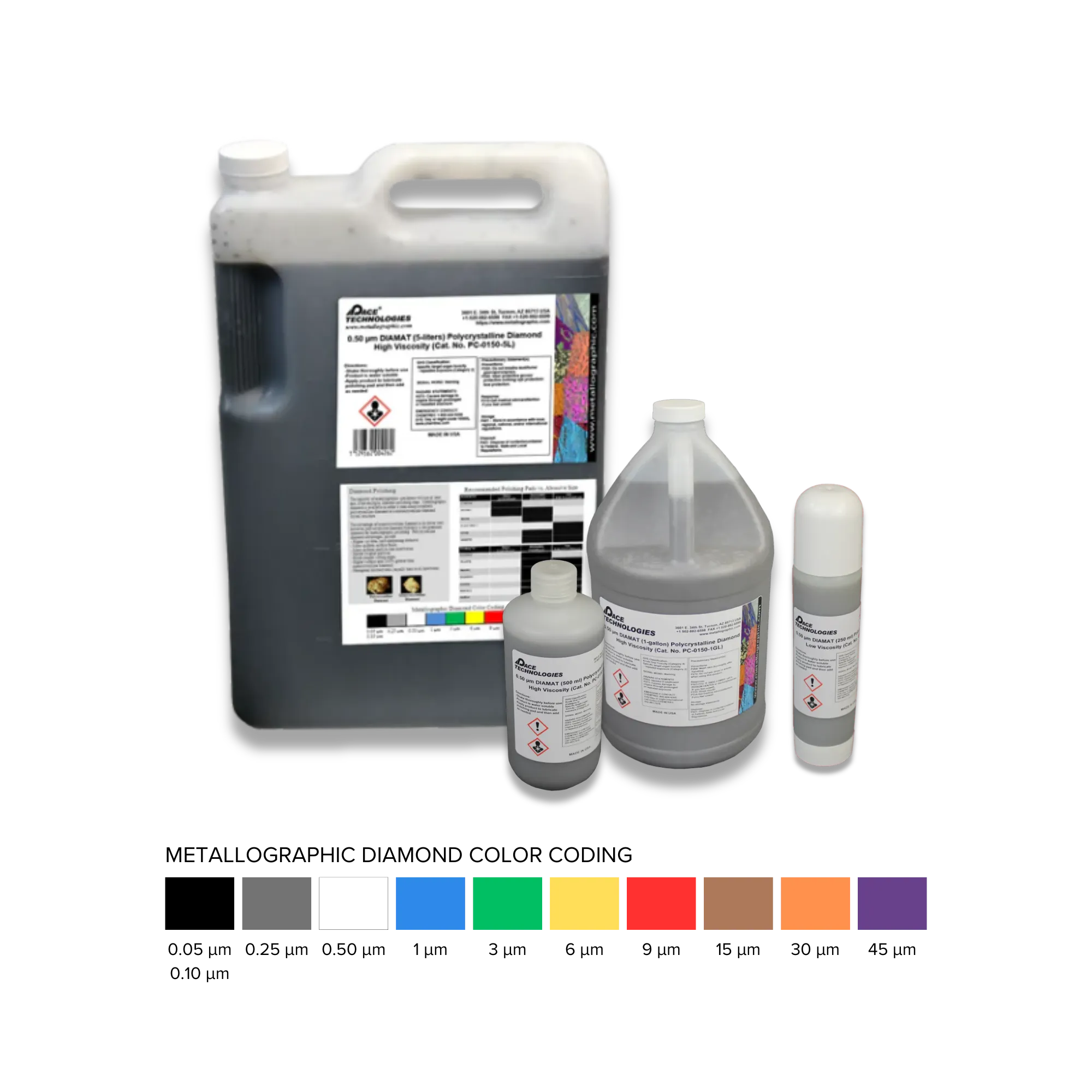
Polycrystalline diamond compound is essential for polishing ceramics. Extended polishing times are required at each step.
Medium to hard polishing pads are recommended for ceramics to maintain flatness and avoid pullout.
Diamond Polishing Sequence
Use polycrystalline (DIAMAT or equivalent) diamond suspensions throughout; PCD's multi-point cutting cuts harder ceramics more efficiently than monocrystalline diamond and produces less grain pullout. Pad stiffness decreases as abrasive size decreases.
- 9 μm DIAMAT polycrystalline diamond on TEXPAN (firm, non-woven): 5 minutes, 30 N per sample, 150 RPM, complementary rotation, water-based diamond extender.
- 3 μm DIAMAT on GOLD PAD (low-nap): 3 minutes, 25 N per sample, 150 RPM.
- 1 μm DIAMAT on NYPAD or ATLANTIS (low-nap): 2 minutes, 20 N per sample, 150 RPM.
- 0.05 μm colloidal silica on MICROPAD (high-nap): 1-2 minutes, 10-15 N per sample, 150 RPM. Switch to plain water on the cloth for the last 20-30 seconds to flush silica off the sample. Never let colloidal silica dry on a ceramic surface.
Time guidance: The times above are starting points for typical Class 10 ceramics (Al2O3, ZrO2, dense Si3N4). For the hardest materials (SiC, B4C, dense WC), extend each step by 50-100% or insert an intermediate 6 μm step on TEXPAN. Inspect at 200× between steps; do not run on the clock alone.
Pad Map & Parameters Summary
| Step | Abrasive | PACE Pad | Force / sample | Time |
|---|---|---|---|---|
| Rough polish | 9 μm DIAMAT (PCD) | TEXPAN | 30 N (~7 lbf) | 5 min |
| Intermediate | 3 μm DIAMAT (PCD) | GOLD PAD | 25 N (~5 lbf) | 3 min |
| Intermediate | 1 μm DIAMAT (PCD) | NYPAD or ATLANTIS | 20 N (~4 lbf) | 2 min |
| Final | 0.05 μm colloidal silica | MICROPAD | 10-15 N (~2-3 lbf) | 1-2 min |
- Speed: 150 RPM throughout.
- Rotation: Complementary (head and platen turning in the same direction).
- Lubricant: Water-based diamond extender at the diamond steps. Some ceramics (porous oxides) benefit from low-evaporation extenders to keep the cloth moist.
- Inspect at 200× after each step to verify previous scratches are gone before proceeding.
Grain pullout is the common ceramic polishing problem. If you see pulled-out grains in the polished surface, the fix is, in order, (1) lower the force at the failing step, (2) switch to a firmer pad at that step, (3) extend the previous step rather than the failing one, (4) consider vibratory polishing or ion-beam polishing as the final step.
Vibratory Polishing
Vibratory polishing with colloidal silica for 1-4 hours is an excellent final step for ceramics. The low-energy, multi-directional motion produces flatter, less-pulled-out surfaces than rotary polishing alone, and the chemical-mechanical action of colloidal silica on many ceramics (especially Si3N4 with glassy grain boundary phase, ZrO2, and many oxides) reveals grain boundaries without thermal etching. This is a practical alternative when a high-temperature furnace is not available.
- Setup: 0.05 μm colloidal silica on MICROPAD in the vibratory bowl.
- Sample weight: 100-300 g over the mount.
- Time: 1-2 hours for routine grain-boundary revelation; 4-8 hours for image-analysis-grade surfaces.
- Cleaning: Rinse and air-dry the cloth between samples; vibratory pads accumulate ceramic debris that scratches subsequent samples.
Ion-Beam Polishing
For extremely hard ceramics or when persistent grain pullout makes mechanical polishing impractical, broad ion-beam milling produces pullout-free surfaces by removing material with argon ions rather than mechanical abrasion. Standard final step for SEM/EBSD analysis of dense SiC, B4C, and ZrB2. Requires specialized equipment (BIB mill).
For more information on polishing supplies, visit our Diamond Abrasives and Polishing Pads collections.
Etching
Ceramic "etching" covers three distinct techniques that the literature lumps together but that differ fundamentally in mechanism, hazard, and equipment:
- Polishing-induced contrast and optical revelation: no actual etching, but often sufficient. DIC and dark-field illumination on a well-polished surface reveal grain boundaries in many ceramics without any chemical or thermal treatment.
- Thermal etching: heating below the sintering temperature so grain boundaries develop via surface diffusion. The standard method for sintered structural ceramics when equipment is available.
- Chemical and molten-salt etching: boiling concentrated acids or molten salt baths. Most hazardous of the three; use when DIC/dark-field and thermal etching are not options.
Try optical revelation first. Many ceramic preparations need no etching at all. Examine the as-polished sample under DIC and dark-field before reaching for the furnace or fume hood. Vibratory polishing with colloidal silica also produces grain-boundary contrast in many ceramics through chemical-mechanical action, without thermal etching.
Optical Revelation (No Etching)
For ceramics with multiple phases, porosity, or anisotropic crystal structure, the as-polished surface often shows grain boundaries clearly under the right illumination. This is the preferred approach for routine inspection because it preserves the sample for further analysis and avoids the hazards of thermal or chemical etching.
- DIC (Differential Interference Contrast): The single most useful technique for ceramics. Reveals grain boundaries and crystal orientation in many materials without etching, using nanometer-scale surface height differences from polishing.
- Dark-field microscopy: Outstanding for finding cracks, pores, and inclusions in ceramics. Often used in failure analysis as the first inspection method.
- Polarized light: Useful for anisotropic ceramics; many SiC polytypes, alumina, and zirconia phases produce striking color contrast under crossed polarizers.
- Brightfield: Best for ceramics with strong compositional contrast (multi-phase composites, ceramics with metallic inclusions).
Thermal Etching
Thermal etching is the most common method for revealing grain boundaries in ceramics. The sample is heated to a temperature below the sintering temperature (typically 100-200°C below) for a specific time, which causes grain boundaries to become visible through surface diffusion.
Thermal Etching Procedure
- Ensure sample is clean and dry after final polishing - any contamination will affect results
- Place sample in a furnace preheated to the appropriate temperature (typically 100-200°C below sintering temperature)
- Use appropriate atmosphere (air, vacuum, or controlled atmosphere depending on ceramic)
- Heat for 30 minutes to 2 hours (time and temperature depend on ceramic type and grain size)
- Cool slowly to room temperature (furnace cool or controlled cooling rate) to avoid thermal shock
- Inspect under microscope - grain boundaries should be visible. Adjust time/temperature if needed
Important: Thermal etching can alter the microstructure if temperature is too high or time is excessive. Always stay well below the sintering temperature. For fine-grained ceramics, shorter times and lower temperatures are typically sufficient.
Typical Thermal Etching Conditions
- Alumina (Al₂O₃): 1400-1500°C for 30-60 minutes in air. Fine-grained alumina may require shorter times (20-30 minutes)
- Zirconia (ZrO₂): 1200-1300°C for 30-60 minutes in air. Be careful with temperature to avoid phase transformation
- Silicon Carbide (SiC): 1800-1900°C for 30-60 minutes in inert atmosphere (Ar or N₂). Air will cause oxidation
- Silicon Nitride (Si₃N₄): 1400-1500°C for 30-60 minutes in N₂ atmosphere. Air will cause decomposition
- Boron Carbide (B₄C): 1800-2000°C for 30-60 minutes in inert atmosphere. Very high temperature required
Atmosphere Considerations: Some ceramics require specific atmospheres for thermal etching. Silicon carbide and silicon nitride will oxidize or decompose in air. Always use the appropriate atmosphere for the ceramic type. Consult material-specific literature for exact conditions.
Safety Warning: Thermal etching requires high-temperature furnaces. Always follow proper safety procedures, use appropriate personal protective equipment, and ensure proper ventilation. Be aware that thermal etching can alter the microstructure if temperature or time is excessive.
Chemical and Molten Salt Etching
Chemical etching is less common for ceramics than for metals, but several effective methods exist for specific ceramic types. Most involve boiling concentrated acids or molten salt baths rather than room-temperature immersion. The correct etchant depends on the ceramic composition; etchants are NOT interchangeable between ceramic types.
Oxide Ceramics (Al₂O₃, ZrO₂)
- Boiling Phosphoric Acid (H₃PO₄): 15 ml H₂O + 85 ml H₃PO₄, boiling, 5 min to 2 hrs. For alumina (Al₂O₃). High-purity alumina requires longer etch times.
- Molten KHF₂ (Potassium Hydrogen Fluoride): Melt in platinum crucible, 5–10 min. For alumina and aluminosilicates (mullite). Releases HF fumes; extreme hazard.
- Boiling Sulfuric Acid (H₂SO₄): 50 ml H₂O + 50 ml H₂SO₄, boiling, 1–5 min. For zirconia (ZrO₂). Always add acid to water.
Carbide Ceramics (SiC, WC, TiC)
- Molten Na/K Bicarbonate: NaHCO₃ or KHCO₃ melt in platinum crucible, ~10 min. For silicon carbide (SiC).
- Murakami's Reagent: 10 g K₃Fe(CN)₆ + 10 g KOH + 100 ml water, immerse 3–10 min at RT. For tungsten carbide (WC) and titanium carbide (TiC). Do NOT acidify (releases HCN).
- HCl + H₂O₂ (30%): 10 ml + 10 ml, seconds to minutes. Alternative for WC; more aggressive than Murakami's.
Nitride Ceramics (Si₃N₄)
- Molten KOH: Melt KOH in platinum or nickel crucible, seconds to minutes. Preferentially attacks the glassy intergranular phase.
- Concentrated HF (48–50%): Immerse for 10–15 min at room temperature. Attacks the glassy grain boundary phase. Extreme HF hazard.
Boride Ceramics (ZrB₂, TiB₂)
- Lactic-Nitric-HF: 30 ml lactic acid + 10 ml HNO₃ + 10 ml HF, seconds to minutes. Contains HF; extreme hazard.
Safety Warning: Many ceramic etchants involve extreme hazards: hydrofluoric acid (HF) causes deep tissue burns that may not be immediately painful; HF-rated gloves and calcium gluconate gel are mandatory. Molten salts and boiling acids cause severe burns. Murakami's Reagent contains potassium ferricyanide; never acidify (releases HCN gas). Always work in a fume hood with appropriate PPE. Thermal etching avoids these chemical hazards and is preferred when equipment is available.
Chemical Etching Procedure
- Ensure sample is clean and dry. Residual colloidal silica gives mottled etch results.
- Apply etchant by swab for milder reagents; immerse for the boiling-acid and molten-salt etches per the recipes above.
- Etch for the time appropriate to the reagent and ceramic. Start at the short end of the range and check progress.
- Rinse immediately with water, then ethanol. For HF-containing etches, dilute and neutralize per HF safety protocol before disposal.
- Dry with compressed air.
Order of preference: optical revelation (DIC/dark-field) → vibratory polish with colloidal silica → thermal etching → chemical etching. Use the least hazardous method that reveals what you need.
Troubleshooting
Common Issues and Solutions
Problem: Chipping During Sectioning
Symptoms: Chips or cracks visible at edges after sectioning
Solutions: Reduce cutting speed further (try 30-50 RPM), use diamond blades, reduce feed rate, ensure proper sample support, use copious coolant, consider multiple shallow passes instead of one deep cut
Problem: Cracking During Mounting
Symptoms: Cracks visible in sample after mounting
Solutions: Use castable mounting instead of compression mounting, reduce mounting temperature, allow slower cooling, ensure sample is not stressed before mounting
Problem: Scratches Not Removing
Symptoms: Scratches from previous grit still visible after grinding/polishing
Solutions: Extend grinding/polishing time at each step (ceramics require much longer times), ensure using diamond abrasives (not SiC), use fresh abrasives, check that all scratches are removed before proceeding to next grit, rotate sample 90° between grits
Problem: Grain Boundary Pullout
Symptoms: Holes or pits at grain boundaries, missing grains
Solutions: Reduce polishing pressure, extend polishing times, use softer polishing cloths for final steps, avoid over-polishing, use colloidal silica for final polish
Problem: No Grain Boundaries Visible
Symptoms: Flat, featureless surface after polishing, no contrast
Solutions: Try thermal etching (most common for ceramics), check if grain boundaries are visible with different lighting (DIC, polarized light), some ceramics may not show grain boundaries easily, ensure proper polishing to avoid artifacts that obscure structure
Problem: Excessive Preparation Time
Symptoms: Preparation taking much longer than expected
Solutions: This is normal for ceramics - they require extended times at each step (especially SiC and B₄C). Ensure using diamond abrasives throughout (not SiC), use fresh abrasives, use polycrystalline diamond for more aggressive cutting, maintain consistent pressure, but accept that ceramics simply take longer than metals. For hardest ceramics, consider ion beam polishing as an alternative for final steps.
Problem: Porous Ceramic Pullout
Symptoms: Material pulling out from pores, holes in microstructure
Solutions: Use vacuum impregnation during mounting to fill pores completely, use low-viscosity epoxy resin, ensure proper vacuum level and time, use lighter polishing pressure, consider using mounting material with similar hardness to ceramic to prevent relief
Problem: Phase Transformation (Zirconia)
Symptoms: Cracking or microstructural changes in zirconia samples
Solutions: Use lower cutting speeds during sectioning, avoid excessive pressure during grinding/polishing, use castable mounting instead of compression mounting, avoid thermal etching at temperatures that cause phase transformation, use gentle preparation techniques throughout
Problem: Thermal Etching Not Working
Symptoms: No grain boundaries visible after thermal etching
Solutions: Increase temperature (but stay below sintering temperature), extend etching time, ensure proper surface finish before thermal etching, some ceramics may require very specific conditions - consult literature for your specific ceramic type
Additional Reading
- Zipperian, D.C. Metallographic Handbook. PACE Technologies, Tucson, AZ. House reference for prep procedures.
- ASM Handbook, Vol. 9: Metallography and Microstructures. ASM International. Sections on ceramics preparation, thermal etching, and chemical etchants.
- Weidmann, E. and Guesnier, A. "Metallographic preparation of thermal spray coatings." Struers Application Notes. Relevant for ceramic coatings, vacuum impregnation, and the fluorescent-dye porosity-visualization technique.
- Weidmann, E., Guesnier, A., and Bundgaard, H. "Metallographic preparation of microelectronics." Struers Application Notes. Relevant for multilayer ceramic capacitors and ceramic-on-metal interfaces.
- Petzow, G. Metallographic Etching, 2nd ed. ASM International. Comprehensive ceramic etchant reference, including thermal and molten-salt etching procedures.
- ASTM E1920 — Standard Guide for Metallographic Preparation of Thermal Sprayed Coatings (procedural parallels apply to bulk ceramics).
- ASTM C1326 / C1327 — Standard Test Methods for Knoop and Vickers Indentation Hardness of Advanced Ceramics.
- ASTM E1245 — Automatic Image Analysis (for porosity and grain size measurement on ceramics).
- Chinn, R.E. Ceramography: Preparation and Analysis of Ceramic Microstructures. ASM International / Wiley. The definitive ceramic-specific metallography reference.
Explore More Procedures
Browse our comprehensive procedure guides for material-specific preparation methods and get personalized recommendations.