Metallography reference

Metallographic Specimen Preparation Basics

Metallography is the study of a material's microstructure. Analyzing the microstructure helps determine whether the material was processed correctly, and it is therefore a critical step in determining product reliability and in figuring out why a material failed.

The basic steps for proper metallographic specimen preparation are documentation, sectioning, mounting, planar grinding, rough polishing, final polishing, etching, microscopic analysis, and hardness testing.

Documented metallographic specimen on a microscope stage

Step 01

Documentation

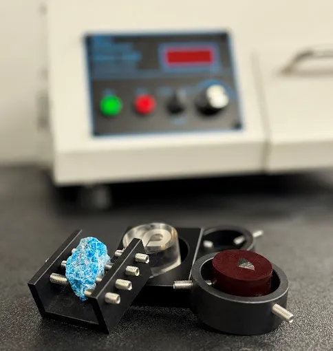
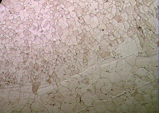
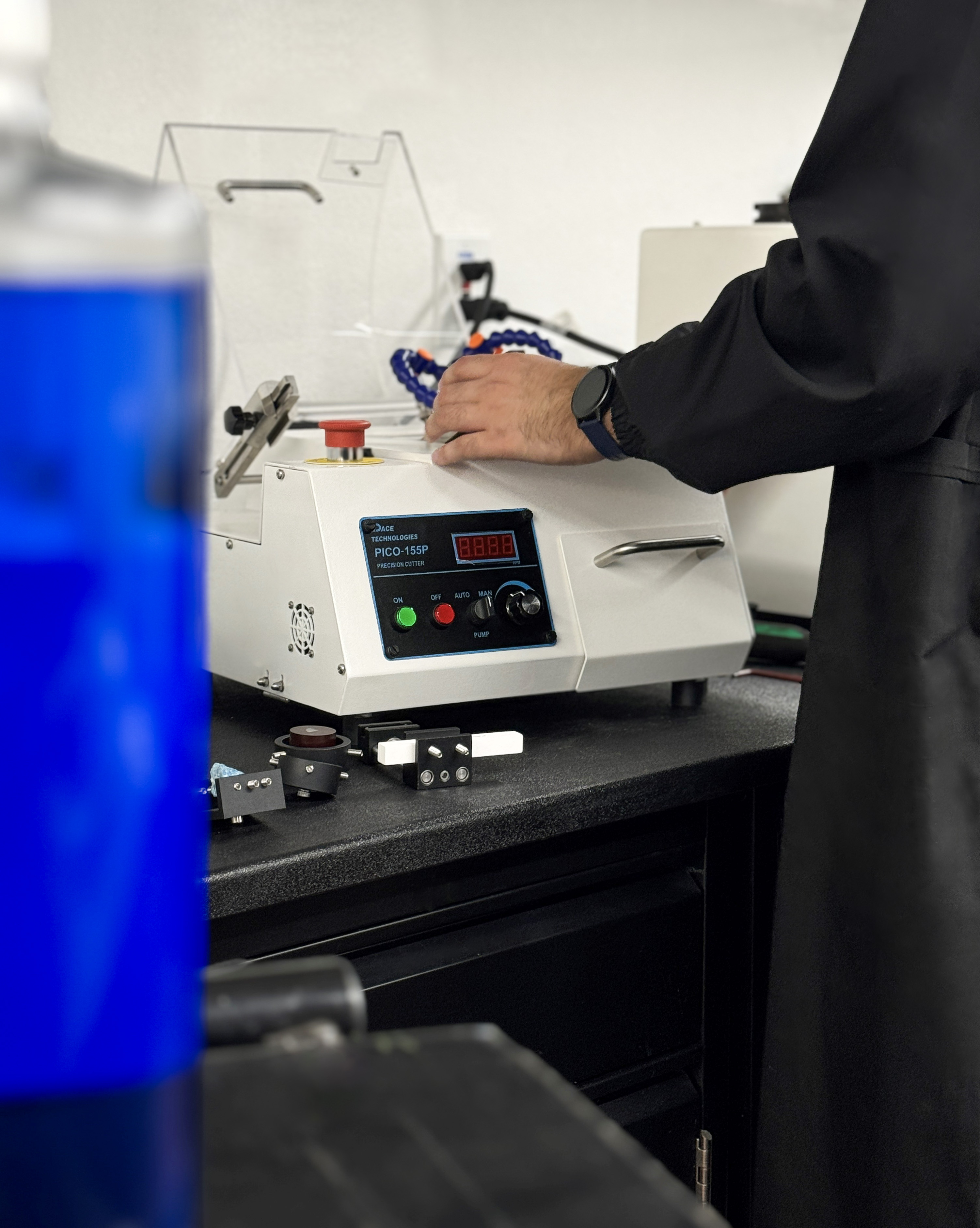
Metallographic analysis is a valuable tool. Properly documenting the specimen's initial condition and the microstructural analysis that follows turns metallography into a powerful quality control instrument and an invaluable investigative tool.

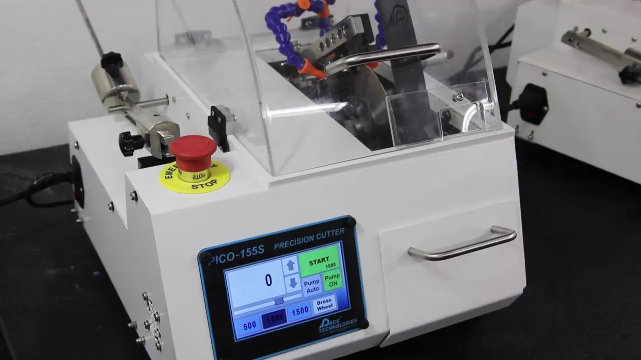
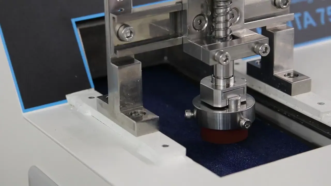
Before any blade touches the part, photograph and label the as-received condition, record the orientation, and note any visible damage. In failure analysis the chain of evidence matters as much as the final image.

Abrasive sectioning of a metallographic sample

Step 02

Sectioning

Most specimens need to be cut down to the area of interest before they can be prepared. Depending on the material, that means abrasive cutting for metals and metal-matrix composites, diamond wafer cutting for ceramics, electronics, biomaterials, and minerals, or thin sectioning with a microtome for plastics.

Proper sectioning is required to minimize damage, which can alter the microstructure and produce a false characterization downstream. The right combination of abrasive type, bond, grit, cutting speed, load, and coolant is what keeps the cut from telling you a story that isn't there.

Abrasive blade selection guidelines
MaterialClassificationAbrasive / Bond
Aluminum, brass, zincSoft non-ferrousSiC / Resin
Heat-treated alloysHard non-ferrousAlumina / Resin
< Rc 45 steelSoft ferrousAlumina / Resin
> Rc 45 steelHard ferrousAlumina / Resin
Super alloys, high Ni-CrAllSiC / Resin
General purposeAlumina / Resin (rubber bonded)
Compression mounting of metallographic specimens

Step 03

Mounting

Mounting does three things at once: it protects the specimen edge and preserves surface features, it fills voids in porous materials, and it makes irregular shapes easier to handle, which matters most in automated preparation.

For metals, compression mounting is by far the most common approach. Phenolics dominate on cost. Diallyl phthalates and epoxies are chosen when edge retention is critical. Acrylics are chosen when you need to see through the mount. For brittle or porous materials, castable resins are typically a better fit.

Compression mounting resin properties
Property Phenolics Acrylics Epoxy (glass filled) Diallyl phthalates
CostLowModerateModerateModerate
Ease of useExcellentModerateGoodGood
Cycle timeExcellentModerateGoodGood
Edge retentionFairGoodExcellentExcellent
ClarityNoneExcellentNoneNone
HardnessLowGoodHighHigh
Planar grinding of a metallographic specimen

Step 04

Planar Grinding

Planar grinding (sometimes called coarse grinding) does two jobs at once: it flattens the specimen and removes the damage left by sectioning. The trick is doing both without creating worse damage than you started with, especially on brittle materials like silicon.

Three machine parameters control the outcome: applied pressure, the relative velocity between head and platen, and the direction of grinding. Higher pressure removes more stock but creates more subsurface damage. Higher relative velocity is aggressive but uneven. Matching head and platen speed in the same direction is gentle and uniform, which is what you want when retaining inclusions and brittle phases matters more than throughput.

Common abrasive grit sizes and median particle diameter
European (P-grade) Standard grit Median diameter (µm)
6060250
120120106
P24024058.5
P32028046.2
P40035
P60040025.75
P100050018.3
P120060015.3
P24008006.5
P400012002.5
Rough polishing on a low-nap cloth with diamond suspension

Step 05

Rough Polishing

Rough polishing exists to remove the damage that planar grinding left behind. Done correctly, it preserves the specimen's flatness and keeps inclusions and secondary phases in place, leaving only cosmetic damage for the final step to clean up.

This is diamond's territory. Most procedures step from 9 µm down to 1 µm on low-nap polishing cloths. Polycrystalline diamond is preferred over monocrystalline because its many small cutting edges produce higher cut rates with less subsurface damage.

Final polishing on a high-nap cloth with colloidal alumina

Step 06

Final Polishing

Final polishing is a finishing pass, not a damage-removal pass. If damage from cutting or grinding is still visible at this stage, the answer is to go back, not to polish harder.

For most metals, that means a brief pass on a high-napped cloth with colloidal alumina, kept under 30 seconds. Ceramics and ceramic matrix composites benefit from alternating colloidal silica and 1 µm polycrystalline diamond, which produces a chemical-mechanical polishing effect and a damage-free surface.

Polishing cloth selection guide
ClothTypeTypical use
Metal meshWire mesh, semi-fixed abrasiveCoarse and intermediate lapping
POLYPADPolyesterIntermediate polishing
TEXPAN (Pellon)Low napMost common intermediate; ceramic final
BLACKCHEM 2Porometric polymerBetween low and high nap
DACRON (Nylon)High napFinal polish for metals and polymers
MICROPAD / NAPPADHigh napMost common final polish for metals
Chemical etching to reveal microstructure

Step 07

Etching

Etching is what makes the microstructure visible. It selectively attacks features (grain boundaries, phases, inclusions) based on composition, stress, or crystal structure, so that the differences in optical reflectivity are large enough to read at the microscope.

Chemical etching is the most common technique, with hundreds of formulations developed for specific alloys. Electrolytic, molten salt, thermal, and plasma etching all have their niches for materials that don't respond well to ordinary chemical attack.

Common chemical etchants
EtchantCompositionApplicationConditions
Keller's190 mL H₂O, 5 mL HNO₃, 3 mL HCl, 2 mL HFAluminum alloys10-30 sec immersion, fresh only
Kroll's92 mL H₂O, 6 mL HNO₃, 2 mL HFTitanium15 sec
Nital100 mL ethanol, 1-10 mL HNO₃Carbon steel, tin, nickel alloysSeconds to minutes
Kalling's No. 240 mL H₂O, 2 g CuCl₂, 40 mL HCl, 40-80 mL ethanolStainless, Fe-Ni-Cr alloysFew seconds to minutes
Marble's50 mL H₂O, 50 mL HCl, 10 g CuSO₄Stainless steels, nickel alloysFew seconds, swab or immerse
Vilella's45 mL glycerol, 15 mL HNO₃, 30 mL HClStainless, carbon steel, cast ironSeconds to minutes
Picral100 mL ethanol, 2-4 g picric acidIron and steel, tin alloysSeconds to minutes (do not let dry, explosive)
Microscopic analysis of an etched specimen

Step 08

Microscopic Analysis

With the microstructure revealed, the next step is reading it. The illumination technique you choose changes what's easy to see and what disappears into the background.

For quantitative surface topography, optical interferometry (PSI for resolution, VSI for range) and atomic force microscopy extend metallography from a two-dimensional view into a three-dimensional measurement.

  • Bright field — the metallography default. Flat surfaces appear bright; pores, edges, and etched boundaries appear darker.
  • Dark field — reverses the contrast. Useful when boundaries and inclusions are faint in bright field.
  • DIC — differential interference contrast. Renders height differences as color, ideal for subtle grain and phase boundaries.
  • Interferometry / AFM — quantitative 3D surface topography down to the angstrom level.
Microhardness testing on a polished specimen

Step 09

Hardness Testing

Hardness testing complements microstructural analysis. Hardness correlates to tensile strength, wear resistance, and ductility, so it's a fast way to monitor quality control and to support materials selection decisions.

Microhardness (Knoop or Vickers, 1 to 1000 gram-force) is used for individual phases, small particles, and brittle materials. Rockwell, Brinell, and macro-Vickers cover bulk hardness across the soft-to-very-hard range. The right test depends on the load you can apply and the feature you want to interrogate.

Hardness tester characteristics
Test Penetrator Load (kg) Hardness range Typical application
Rockwell CDiamond cone150Medium to very hardProduction of finished parts
Rockwell B1/16" steel ball100Soft to mediumProduction of finished parts
Brinell10 mm steel ball500-3000Soft to hardProduction of finished parts
VickersDiamond pyramid5-100Very soft to very hardProduction of unfinished parts
MicrohardnessDiamond pyramid0.01-50Very soft to very hardLab investigations; micro-constituents of alloys and ceramics

Keep exploring

Step into the full library of guides, tools, and material-specific procedures.

Need Help Getting Started?

Our technical support team can help you select the right equipment, consumables, and preparation methods for your application.